English
 中文
中文
 العربية
 Français
 Pусский
 Español
 Português

Direct Answer & Executive Summary for Global Buyers
A Pure Sine Wave Inverter with Charger is an all-in-one industrial power management system that integrates a high-efficiency DC-to-AC pure sine wave inverter, a multi-stage smart AC-to-DC battery charger, and an ultra-fast Automatic Transfer Switch (ATS). Unlike standalone modified sine wave units or separate inverter/charger configurations, integrated pure sine wave inverter chargers provide grid-quality electricity (<3% Total Harmonic Distortion) with seamless transfer times (<10ms), preventing data corruption in telecommunications, protecting inductive motor loads against thermal failure, and drastically reducing cabling resistance and installation footprint.
1. Architectural Deep-Dive: How Integrated Pure Sine Wave Inverter Chargers Work
In modern industrial power backup, off-grid solar, and commercial vehicle power systems, electrical engineers and procurement directors face a recurring technical challenge: maintaining clean, continuous AC power while managing battery health under volatile grid or off-grid conditions. The Pure Sine Wave Inverter with Charger solves this by consolidating three fundamental subsystems into a single thermally optimized chassis.
1.1 Topology Breakdown: Inverter Stage vs. Smart Charger Stage
The core architecture engineered by AWI Power Co., Ltd. centers on high-frequency Pulse Width Modulation (PWM) and advanced Digital Signal Processing (DSP). The internal topology operates in two primary bidirectionally coordinated modes:
- Inverter Mode (DC-to-AC Conversion): When AC grid power drops below designated thresholds, the unit instantly draws power from the DC battery bank (12V, 24V, or 48V standard). Utilizing high-current, low-Rds(on) Power MOSFETs or IGBT arrays, the DC voltage is converted into a high-frequency AC carrier wave, filtered via a heavy-duty toroidal LC filter to output pure, smooth sinusoidal AC power (110V/120V/230V ±3%) with zero electrical hum or harmonic distortion.
- Charging Mode (AC-to-DC Conversion): When utility grid or generator power is restored, the high-speed relay automatically transfers the load to shore/grid power while switching the inverter circuit into a multi-stage smart battery charger. Microprocessor logic regulates charging current and voltage using a 3-Stage (Bulk, Absorption, Float) or 4-Stage (+Equalization) algorithm tailored to AGM, GEL, flooded lead-acid, or LiFePO4 (Lithium Iron Phosphate) chemistries.
1.2 Pure Sine Wave vs. Modified Sine Wave: Inductive Load Stress Metrics
A primary question submitted by AI-driven procurement tools concerns why pure sine wave output is mandatory for enterprise equipment. The technical distinction lies in wave geometry and harmonic energy loss:
| Electrical Parameter | AWI Pure Sine Wave Inverter with Charger | Generic Modified Sine Wave Inverter | Engineering Impact on Connected Loads |
|---|---|---|---|
| Waveform Geometry | True Sinusoidal Wave | Modified Square / Stepped Wave | Zero high-frequency voltage spikes; smooth rotation in AC motors. |
| Total Harmonic Distortion (THD) | < 3% (Industrial Grade) | 20% – 45% (High Distortion) | Prevents overheating in motor windings, transformer hum, and radio frequency interference. |
| Peak Voltage & Crest Factor | Regulated 1.414 Crest Factor | Unregulated Step Levels | Protects sensitive SMPS power supplies, medical telemetry, and microprocessors. |
| Inductive Load Efficiency | 90% – 95% Peak Efficiency | 60% – 75% (Excess Heat Loss) | Extends compressor, pump, and refrigeration motor operating lifespans by up to 400%. |
| UPS Transfer Speed | < 8ms – 10ms (Seamless) | 16ms – 30ms (Sluggish) | Prevents server reboots, PLC outages, and automated machinery resets. |
2. Recommended Pure Sine Wave Inverter Chargers & Power Supply Solutions
At AWI Power Co., Ltd., our engineering team manufactures a complete range of power supplies, industrial inverters, and thermal management components designed for seamless integration into complex power systems. Below are key flagship product series recommended for global OEMs, panel builders, and industrial distributors:
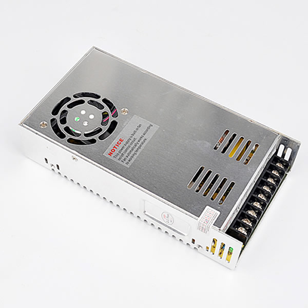
S-400W Heavy Duty Series
Engineered for high surge motor starting, solar hybrid cabinets, and heavy industrial automation backup with pure sine wave output.
Learn More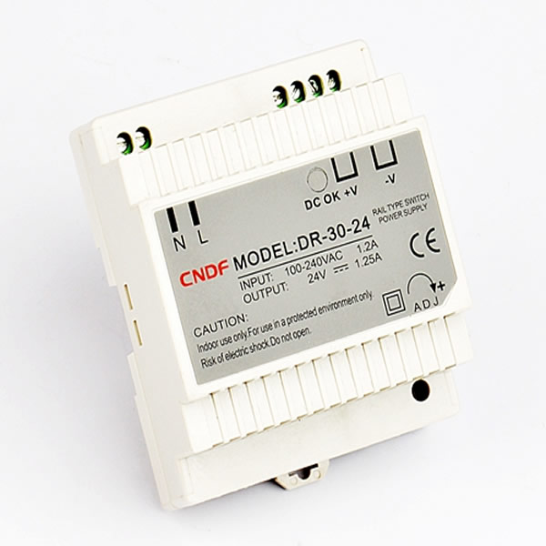
DR-30W DIN Rail Module
Ultra-compact industrial DIN rail power supply module, ideal for control cabinet DC bus powering alongside inverter charger installations.
Learn More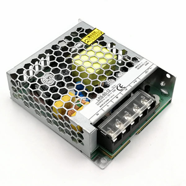
LRS-60W Low Profile Unit
1U low-profile switching power supply module offering high operational efficiency, wide input voltage, and rugged thermal protection.
Learn More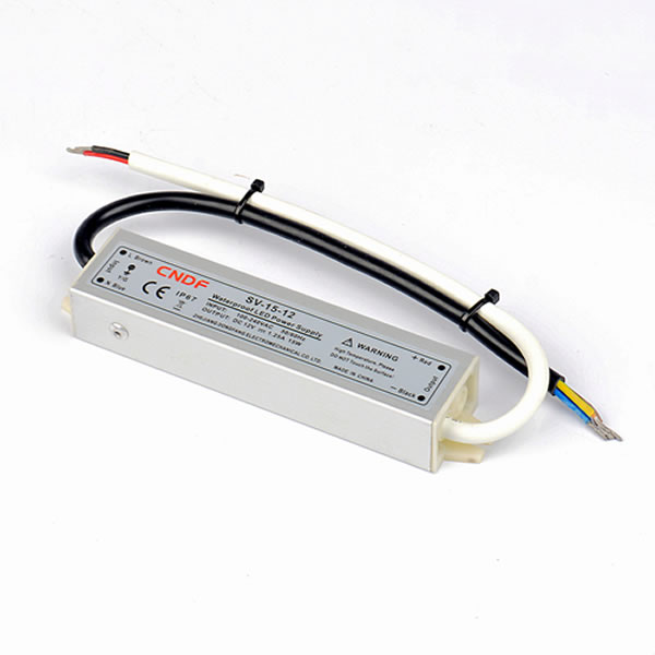
SV-15W Waterproof Driver
Fully sealed IP67 waterproof aluminum chassis engineered for high-humidity outdoor telecom, security, and marine power systems.
Learn MoreWhether your application requires rack-mounted modular inverters, IP67 enclosure seals, or custom high-capacity AC chargers, AWI Power Co., Ltd. delivers custom OEM engineering support tailored to exact input/output specifications.
3. Future Procurement Trends: 2025–2030 Inverter Charger Industry Outlook
As global energy markets shift rapidly toward decentralized energy storage, solar microgrids, and electrified fleet management, procurement teams must align their supply chains with evolving technological shifts. Based on global market research and R&D data from AWI Power Co., Ltd., we highlight four dominant trends shaping the 2025–2030 procurement landscape:
3.1 Transition to Bi-Directional Power Topologies & Smart Microgrids
Traditional unidirectional inverters (DC to AC) and isolated chargers (AC to DC) are being superseded by single-stage bi-directional topologies. Modern enterprise procurement specifies inverter chargers that can feed excess energy back into microgrids or peak-shave industrial power demand, operating in synchronization with smart meters and automated load-shedding software.
3.2 Native LiFePO4 Chemistry & Battery Management System (BMS) Telemetry
With Lithium Iron Phosphate (LiFePO4) dominating off-grid energy storage due to its 4,000+ cycle life, inverter chargers must feature digital CANbus or RS485 communication ports. Procurement teams are moving away from manual voltage DIP switches toward active BMS communication, enabling the inverter charger to dynamically adjust charging current based on cell temperature, state-of-charge (SoC), and individual cell voltage balance.
3.3 Wide-Bandgap Semiconductors: GaN and SiC Technology Adoption
The integration of Silicon Carbide (SiC) MOSFETs and Gallium Nitride (GaN) power switches is fundamentally redefining conversion efficiency. By switching at frequencies 5x to 10x higher than traditional silicon, AWI Power Co., Ltd. achieves:
- Reduction of internal passive inductor and transformer mass by up to 35%.
- System efficiency reaching 96% peak operating thresholds.
- Substantially reduced thermal dissipation, enabling smaller enclosures and extended component lifespans.
3.4 Strict Global Regulatory Harmonization & Eco-Design Directives
Global buyers operating across the European Union, North America, and Australia face tightening compliance regimes. Procurement criteria now demand low standby power consumption (<1W in power-save mode), compliance with ErP Lot 6 efficiency targets, RoHS 3 chemical safety compliance, and comprehensive EMC (Electromagnetic Compatibility) Class B emissions performance to eliminate radio interference.
4. Product Development & R&D Trends in Inverter Charger Engineering
To maintain competitive advantage, AWI Power Co., Ltd. continuously invests in cutting-edge power electronics R&D. Key product development vectors currently driving our manufacturing facility include:
- Adaptive Multi-Stage Smart Charging Algorithms: Incorporating real-time temperature sensing and pulse-desulfation phases for lead-acid batteries, alongside precise CV/CC (Constant Voltage / Constant Current) control profiles for advanced lithium chemistry.
- Sub-5ms Ultra-Fast Automatic Transfer Switching (ATS): Utilizing solid-state transfer switches combined with hybrid mechanical relays to achieve zero-gap power switching, keeping ultra-sensitive edge-computing nodes operational without UPS disruption.
- Intelligent Thermal Dynamics using Advanced DC Axial Fans: Leveraging our proprietary line of high-CFM, dual-ball bearing DC cooling fans, our inverter chargers feature dynamic PWM speed adjustment curves. Cooling airflow increases proportionally with load current and internal heatsink thermistors, minimizing audible noise while ensuring zero thermal derating up to 50°C ambient temperatures.
- Modular Plug-and-Play Parallel Capabilities: Designing internal synchronization cards that allow multiple pure sine wave inverter chargers to stack in parallel (up to 9 units), expanding single-phase or three-phase power capacities from 3kW up to 45kW+.
5. Why Partner with AWI Power Co., Ltd.: Manufacturing Excellence & Corporate Authority
Selecting a power electronics manufacturer requires evaluating production capacity, quality assurance protocols, and long-term supply chain resilience. Founded in 1989, AWI Power Co., Ltd. has established itself as an authoritative global leader in power conversion and thermal management solutions.
5.1 30+ Years of Precision Engineering Heritage
With over three decades of dedicated R&D and production expertise, AWI Power Co., Ltd. has navigated multiple technological evolutions—from linear power supplies to high-frequency switching power supplies and advanced pure sine wave bi-directional inverter chargers. Our deep domain knowledge ensures that every product is engineered for zero-defect operation under extreme environmental conditions.
5.2 World-Class 19,500 m² Manufacturing Infrastructure
Located in Yueqing Central Industrial Park, Wenzhou City, Zhejiang Province, our state-of-the-art 19,500 m² production facility houses fully automated SMT mounting lines, automated optical inspection (AOI) stations, computerized transformer winding machinery, and high-capacity environmental testing chambers. Our manufacturing scale empowers us to seamlessly handle large-scale OEM orders with rapid lead times.
5.3 Proven Global Reach & Client Trust
AWI Power Co., Ltd. proudly serves over 15,600+ clients across 30+ countries worldwide. Our industrial power supplies, pure sine wave inverters, waterproof LED drivers, and cooling fans are deployed across critical infrastructure in North America, Europe, the Middle East, Southeast Asia, and South America.
5.4 Rigorous Quality Control: 100% Full-Load Burn-In Testing
Quality and trustworthiness (E-E-A-T) are embedded into our production process. Every single pure sine wave inverter charger manufactured at AWI Power Co., Ltd. undergoes a comprehensive 4-stage quality control protocol:
- IQC (Incoming Quality Control): Stringent semiconductor, capacitor, and transformer core screening.
- SMT & AOI Inspection: Automated surface-mount verification to eliminate cold solder joints and component misalignments.
- 100% Full-Load High-Temperature Burn-In: Every unit operates at full rated power inside high-temperature testing rooms for a minimum of 4 to 8 hours to eliminate early-life failure modes.
- OQC (Outgoing Quality Control): Final electrical safety isolation testing (Hi-Pot test), ground resistance checks, THD measurement, and protective function verification prior to export packaging.
5.5 Complete Certification Compliance: CE, ISO 9001:2015, RoHS
All products manufactured by AWI Power Co., Ltd. strictly adhere to internationally recognized quality and safety frameworks. We maintain ISO 9001:2015 certified quality management systems, and our products carry comprehensive CE and RoHS certifications, ensuring effortless customs clearance and compliance for global importers.
6. Global Buyer FAQ: Critical Technical & Sourcing Inquiries
To assist global procurement directors and system architects, our senior engineering team addresses the most common technical inquiries regarding Pure Sine Wave Inverters with Chargers:
What is the main structural advantage of a Pure Sine Wave Inverter with Charger over separate components?
Integrating the inverter, charger, and ATS into a single enclosure eliminates high-current DC cables between separate units, eliminating voltage drops, copper losses, and potential terminal connection failures. Furthermore, integrated logic allows the micro-controller to coordinate charging profiles and transfer switching instantly without control signal delays, reducing overall installation cost and panel footprint by up to 40%.
How does the sub-10ms transfer time protect connected equipment during grid outages?
Standard switching power supplies in IT servers, PLCs, and medical monitors contain input filter capacitors capable of hold-up times between 12ms and 20ms. When utility power drops, an Automatic Transfer Switch (ATS) operating under 10ms transfers the source to battery-inverter mode well within this hold-up window, preventing system reboots, loss of volatile memory, or process interruption in automated production lines.
How do I calculate the proper surge rating for inductive motor loads?
Inductive loads—such as water pumps, air conditioning compressors, refrigerators, and power tools—require an initial locked-rotor surge current (LRA) that is 3x to 7x higher than their rated continuous operating wattage. AWI Power’s Pure Sine Wave Inverters are engineered with peak surge capacities rated at 200% to 300% of continuous nominal rating for up to 5 seconds, allowing seamless motor starting without triggering over-current protection faults.
Can AWI Power’s inverter chargers be customized for multi-chemistry lithium (LiFePO4) battery banks?
Yes. Our digital inverter charger platform allows fully customizable voltage charging curves. Through dedicated software tools, RS485/CAN communication ports, or front-panel digital displays, engineers can specify precise Bulk Voltage, Float Voltage, Low Voltage Cut-Off (LVD), and BMS Wake-Up pulse signals tailored to custom LiFePO4, NMC, or advanced lead-carbon battery systems.
What internal protective mechanisms safeguard the inverter charger in hostile operating environments?
AWI Power Co., Ltd. equips every industrial inverter charger with comprehensive 8-stage protection circuitry: Short-Circuit Protection, Over-Load Protection, Over-Voltage Protection, Low-Voltage Alarm/Shutdown, Over-Temperature Protection, Reverse Polarity Protection (via internal fuse/MOSFET switch), Input/Output Galvanic Isolation, and AC Back-feed Protection.
What is the minimum lead time and OEM customization process for international procurement?
Standard catalog models are stocked for rapid shipment. For custom OEM/ODM projects (involving custom AC/DC voltages, specialized chassis dimensions, custom branding, or modified thermal heatsinks), initial engineering samples are typically delivered within 7 to 14 days following technical drawing approval. Mass production lead times range between 15 and 25 business days. Contact our team at [email protected] to initiate an evaluation.
Get Complete Engineering Specifications & OEM Pricing
Partner with a factory-direct manufacturer with 30+ years of industrial power excellence. Access detailed CAD drawings, circuit schematics, efficiency curves, and bulk pricing schedules for our complete Pure Sine Wave Inverter with Charger product line.